Reference: https://developer.android.com/media/platform/hdr-image-format
Identifying UltraHDR
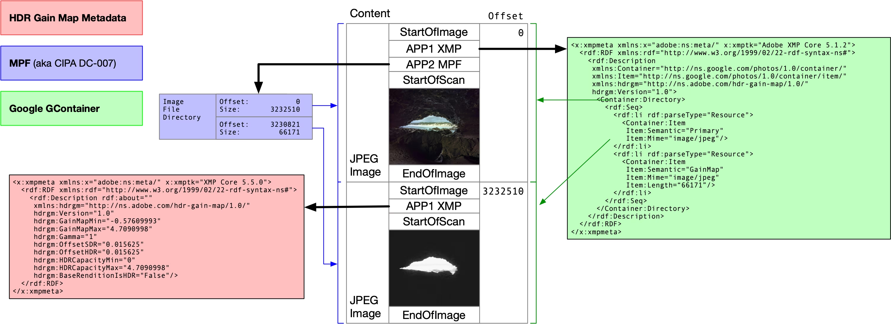
The first JPEG stream in the file is the primary image. In the primary image’s APP1, look for an XMP packet, and inside it check for hdrgm:Version="1.0", where hdrgm is the namespace identifier http://ns.adobe.com/hdr-gain-map/1.0/. If present, the file can be considered compliant with UltraHDR. For strict UltraHDR (Google’s spec), the XMP packet should also include GContainer content, which describes the parts contained in the container, such as the Primary and the GainMap, and their data lengths.
For example, below is the first XMP packet from a JPG shot on an OPPO Find X6 Pro, which meets UltraHDR and GContainer requirements.
<x:xmpmeta
  xmlns:x="adobe:ns:meta/"
  x:xmptk="Adobe XMP Core 5.1.2">
  <rdf:RDF
    xmlns:rdf="http://www.w3.org/1999/02/22-rdf-syntax-ns#">
    <rdf:Description
      xmlns:Container="http://ns.google.com/photos/1.0/container/"
      xmlns:Item="http://ns.google.com/photos/1.0/container/item/"
      xmlns:hdrgm="http://ns.adobe.com/hdr-gain-map/1.0/"
      hdrgm:Version="1.0">
      <Container:Directory>
        <rdf:Seq>
          <rdf:li
            rdf:parseType="Resource">
            <Container:Item
              Item:Semantic="Primary"
              Item:Mime="image/jpeg"/>
          </rdf:li>
          <rdf:li
            rdf:parseType="Resource">
            <Container:Item
              Item:Semantic="GainMap"
              Item:Mime="image/jpeg"
              Item:Length="401160"/>
          </rdf:li>
        </rdf:Seq>
      </Container:Directory>
    </rdf:Description>
  </rdf:RDF>
</x:xmpmeta>
Old Man: MPF
Compared with the custom GContainer, the more general Multi-Picture Format (MPF) was proposed by CIPA in 2009 to label and organise multiple frames within a single JPEG file, such as low-resolution previews, 3D imaging, burst frames, and so on. Today, MPF is also commonly used to tag and locate the Gainmap in an HDR image. MPF information is stored in the primary JPEG’s APP2 segment, and is organised similarly to EXIF’s IFD structure.
The basic layout of an APP2 segment is as follows:
- Starts with marker FF E2, followed by a 2-byte segment length.
- Then 4 bytes MPF identifier “4D 50 46 00” (i.e. “MPF\0”). From the position after the identifier, define the MPF offset base (base, taken as 0).
- Next 4 bytes are the endianness tag, same as TIFF (for example big-endian is 4D 4D 00 2A).
- After that, 4 bytes give the offset to the first IFD (relative to the MPF base); if the IFD follows immediately, this value is 8.
Inside the MPF IFD:
- 2 bytes for the number of entries.
- Each IFD entry takes 12 bytes; common entries include:
- MPFVersion (type UNDEFINED, count 4, usually ASCII “0100”)
- NumberOfImages (type LONG, count 1)
- MPEntry (type UNDEFINED; the entry itself stores a relative offset to the actual MP Entry array)
- At the end there are 4 bytes for the offset to the “next IFD” (0 if none).
The MP Entry array describes each image in the file. Each entry is a fixed 16 bytes, typically containing: 4-byte attributes, 4-byte image data length, 4-byte data offset (relative to the MPF base, pointing to that image’s SOI), and two 2-byte indices for dependencies (0 if none).
Below is an example (hex) with brief comments:
FF E2 00 58              # APP2 and segment length
4D 50 46 00              # "MPF\0" identifier (the position after it is defined as MPF offset base 0)
4D 4D 00 2A              # Big-endian tag (same as TIFF)
00 00 00 08              # Offset to the first IFD (relative to base), 8 means immediately following
00 03                    # Number of IFD entries: 3
B0 00 00 07 00 00 00 04 30 31 30 30  # MPFVersion: type 07 (UNDEFINED), count 4, "0100"
B0 01 00 04 00 00 00 01 00 00 00 02  # NumberOfImages: type 04 (LONG), value 2
B0 02 00 07 00 00 00 20 00 00 00 32  # MPEntry: type 07, count 32, data offset 0x32
00 00 00 00              # Next IFD offset: none (0)
# MP Entry array (16 bytes per entry)
00 03 00 00  00 5B ED A0  00 00 00 00  00 00 00 00  # Entry 1 (primary): length 0x005BEDA0, offset 0 (primary SOI lies before MPF; offset cannot be negative, so record 0)
00 00 00 00  00 06 1F 08  00 5B E4 87  00 00 00 00  # Entry 2 (Gainmap): length 0x00061F08, offset 0x005BE487 (relative to MPF base, points to the second JPEG stream's SOI)
In this example:
- The second image (Gainmap) length 0x00061F08 matches the Gainmap size recorded in XMP (401160); its data offset 0x005BE487 points to the second JPEG stream’s SOI, relative to the MPF base.
- The first (primary) lists the full codestream length 0x005BEDA0; because the primary SOI appears before the MPF base, the data offset cannot be negative, so it is written as 0.
For more detail, see CIPA’s official “DC-x007-2009 Multi-Picture Format”.
Deep Dive into Gainmap
Pedantry corner: UltraHDR refers to using GContainer in the primary to mark locations; the Gainmap with XMP is not defined by UltraHDR, but by Adobe’s standard.
Once you’ve determined whether the image conforms to UltraHDR and whether the Gainmap is located via GContainer or MPF, you can then find the Gainmap and its metadata.
A Gainmap also uses XMP to store metadata. In the located Gainmap JPEG stream, look for an APP1 segment with XMP.
<x:xmpmeta
  xmlns:x="adobe:ns:meta/"
  x:xmptk="Adobe XMP Core 5.1.2">
  <rdf:RDF
    xmlns:rdf="http://www.w3.org/1999/02/22-rdf-syntax-ns#">
    <rdf:Description
      xmlns:hdrgm="http://ns.adobe.com/hdr-gain-map/1.0/"
      hdrgm:Version="1.0"
      hdrgm:GainMapMin="0"
      hdrgm:GainMapMax="2.16048"
      hdrgm:Gamma="1"
      hdrgm:OffsetSDR="0"
      hdrgm:OffsetHDR="0"
      hdrgm:HDRCapacityMin="0"
      hdrgm:HDRCapacityMax="2.16048"
      hdrgm:BaseRenditionIsHDR="False"
      hdrgm:OplusScale="4.47065"/>
  </rdf:Description>
</x:xmpmeta>
Again, there’s a namespace hdrgm pointing to Adobe’s Gainmap standard, which records the metadata a Gainmap needs (OplusScale is OPPO’s private field).
Next, using the Gainmap encoding process as a guide, let’s briefly explain these parameters. First, this is a single-channel Gainmap; encoding generally uses the Gainmap to record differences in luminance. Luminance is computed from RGB colour primaries as a weighted combination of RGB pixel values, essentially the second row of the RGB->XYZ matrix (i.e. computing a Y value). For a three-channel case, you operate directly on RGB per channel.
Let Yhdr and Ysdr be the HDR and SDR after conversion to luminance. Both need to be converted to linear space and be on the same scale.
$$ \text{pixel gain} = \frac{Y_{\text{hdr}} + \text{offset hdr}}{Y_{\text{sdr}} + \text{offset sdr}} $$The two offsets serve a few purposes; commonly you can use 1/64 as the offset:
- Ensure Y hdr + offset hdr is always positive for the logarithm.
- Avoid division issues when Y sdr is 0.
- Improve encoding precision in dark regions
Then take log base 2 of pixel gain, and record the GainMapMin and GainMapMax at this point.
When normalising pixel gain to 0-1, UltraHDR uses max/min content boost instead of the recorded Gainmap min/max. The difference stems from the offsets. Personally, I think using the Gainmap values is better. After that, clamp anything outside 0-1.
What is content boost: this controls the brightness of the HDR content and can be defined by the creator. Google uses the term “implementation-defined”. Compared with objectively computing the HDR/SDR brightness ratio, this user-defined parameter enables subjective effects. For example, if you want every HDR pixel to be brighter than its SDR counterpart, set the min content boost to 1.
Next, apply a power function (Gamma) to the normalised pixel gain. In most cases Gamma can be 1; if the Gainmap contains lots of detail, you can use a slightly larger Gamma.
Finally, stretch the 0-1 Gainmap to 0-255 and encode it as a JPEG image. A JPEG quality no lower than 85-90 is recommended.
As for HDR Capacity Min/Max, they represent the display’s HDR capability. I’m not entirely sure why a display-related quantity is stored in the image; perhaps the idea is similar to the “grading display” in HDR video workflows, recording the creator’s display to assist tone mapping. Most of the time, these values are set the same as Gainmap Min/Max.
There’s also a field indicating whether the base image is SDR or HDR, BaseRenditionIsHDR, usually False.
Decoding and tone-mapping
Here we introduce another variable: Display Boost. It records the ratio between the HDR white point and the SDR white point of the current display, similar to Apple’s Headroom. For example, if SDR white is 100 nits and HDR white is 1600 nits, the Display Boost is 16.
It is used during UltraHDR decoding, mainly when Display Boost is less than Content Boost, i.e. the device cannot fully display the HDR brightness of the content. A weight is introduced to control the brightness of the HDR portion so that it remains within the screen’s capability.
The weight is calculated as follows, with all quantities in log2 non-linear space.
$$ \text{weight} = \frac{\text{max display}-\text{min capacity}}{\text{max capacity}-\text{min capacity}} $$Then clamp it to the 0-1 range, where 1 means the device can display the full HDR content. It is applied to G, the log2 result computed earlier from HDR, SDR, and the two offsets.
During encoding:
$$ G = \log_2 \frac{\text{HDR}+k_{\text{hdr}}}{\text{SDR}+k_{\text{sdr}}} $$During decoding:
$$ \text{HDR} = (\text{SDR}+k_{\text{sdr}}) \cdot 2^{G \cdot \text{weight}}-k_{\text{hdr}} $$When the weight is 1, the computed HDR equals the previously encoded HDR. When the weight is less than 1, the HDR you get reduces the Gainmap contribution according to the screen’s actual capability, producing an “in-between” version, down to weight 0 which shows a fully SDR version.
Compatibility with ISO 21496-1
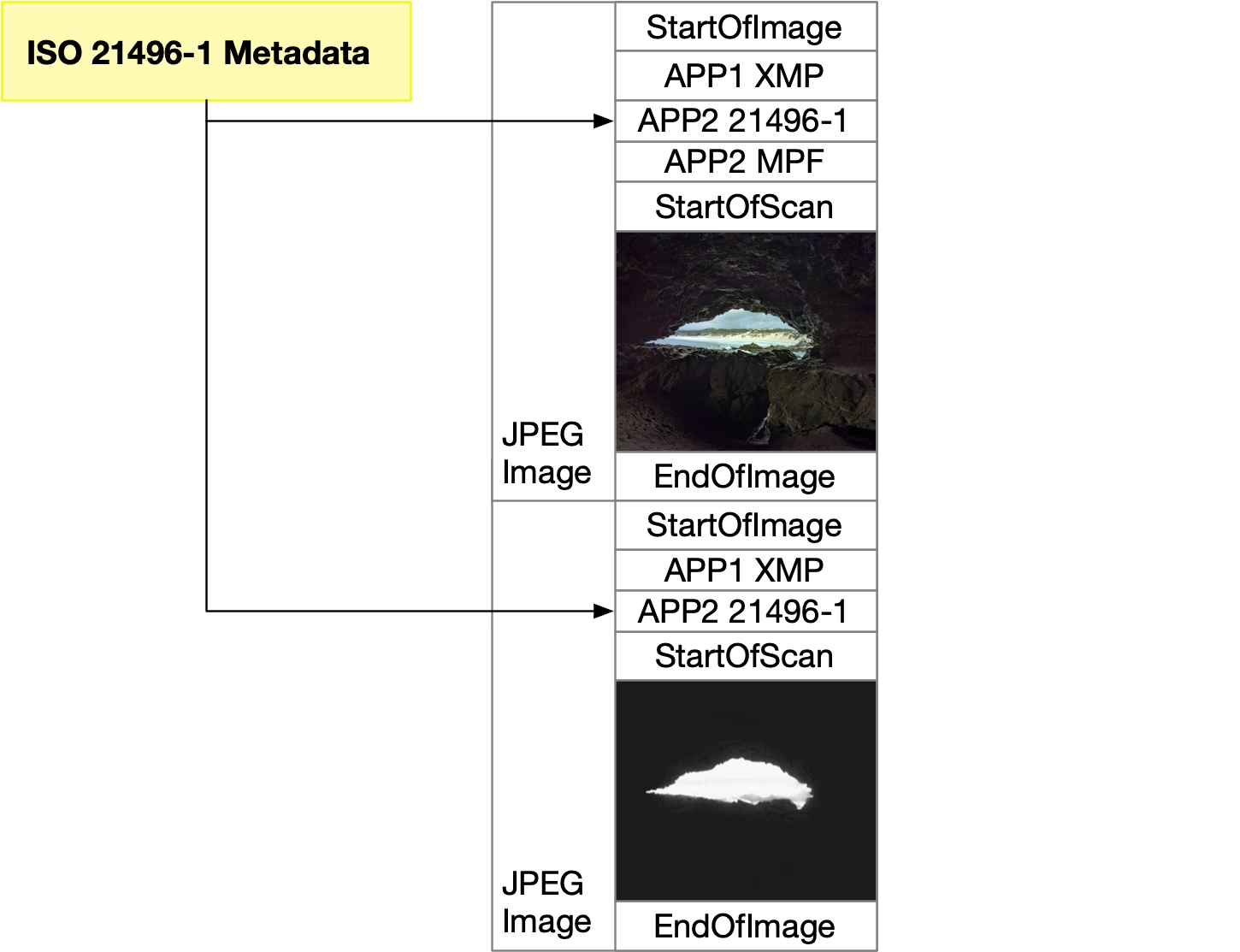
ISO 21496-1 is the international standard for gain-map type HDR still images. It no longer uses XMP in APP1 to store Gainmap metadata; instead it defines a dedicated metadata segment in APP2 to follow the standard. The metadata itself is basically the same.
UltraHDR 1.1 is compatible with ISO 21496-1, which in practice means you have both the XMP in APP1 and the standardised segment in APP2.
The pioneer that ended the Warring States era
Before UltraHDR, dual-layer HDR still images were in a Warring States-era free-for-all: each phone brand had its own standard, and they were mutually incompatible.
Google introduced the UltraHDR standard in Android 13. By using GContainer and MPF to indicate the Gainmap’s location, it helps decoders correctly find the second JPEG frame defined by Adobe’s Gainmap standard. With a very lean approach and minimal changes, it elegantly achieves backwards compatibility.
At present, almost all phone galleries (devices shipping with Android 13 or newer, or iPhones with OLED screens) and Chromium-based browsers can handle this format and most of its variants.
Although it is limited by JPEG’s relatively low compression efficiency, 8-bit depth, and lossy compression, UltraHDR is still a solid upgrade to JPG.
From here, dual-layer HDR formats should gradually move to HEIF, AVIF, or even JPEG XL under the ISO 21496-1 standard. But JPEG, as the most widely used image format, will remain in long-term, heavy use.